

Cobb Breeder Management Guide: Evaporative cooling and light traps
Learn more about evaporative pad management and light trap installationPart of Series:
< Previous Article in Series
Editor's note: This article is an excerpt from the Cobb Breeder Management Guide and additional articles will follow. The Guide was designed to highlight critical factors that are most likely to influence flock performance. The management recommendations discussed were developed specifically for Cobb products. The recommendations are intended as a reference and supplement to your own flock management skills so that you can apply your knowledge and judgement to obtain consistently good results with the Cobb family of products. To read or download the complete Guide or to view Cobb's other management guides, click here.
The primary role of the evaporative cooling system is to maintain house temperature below 28.0 °C (82.4 °F). Enough pad area needs to be installed so fan performance is not severely reduced. For every 1 °C cooling due to the evaporative cooling system, the % RH of the air will increase approximately 4.5 %. (1 °F = 2.5 % RH increase).
Evaporative pad management
- All fans should be on before operating cooling pads!
- The use of evaporative cooling should be evaluated for its effectiveness when outside RH is above 75 %.
- Pads should not be used at temperatures below 28 to 29 °C (82 to 84 °F).
- House humidity not to exceed 85 to 90 %.
- Do not use fogging in conjunction with pads if RH is above 75 %.
- Generally, pads are used from 9 AM to 6 PM due to natural daily humidity cycles – Nighttime operation will increase heat stress.
- Pad system should be flushed weekly.
- Monitor water quality and pH. Maintain hardness levels below 110 ppm and pH in the sump between 7 and 9. Bleed off the system continuously as per manufacturers recommendations. Higher levels of salts will require more frequent bleed-off.
- Do not use pads on a timer cycle to prevent excessive scale buildup on the pad surface.
- Do not use evaporative cooling before 25 days of age. Only during extremely high temperatures, should pads be used with chicks in the first two weeks. Wetting of the pads must be limited with an interval timer. Pads are used only to temper the incoming air.
- Do not cycle the pumps in areas with high levels of salt in the ground water. Continuous drying of the surfaces of the pads will result in rapid formation of scale on the pad surfaces.
- Only use chemicals recommended by the manufacturer.
- DO NOT ADD CHLORINE OR BROMINE.
- Refer to manufactures guidelines.
Common ventilation causes of wet litter and high humidity
- High stocking densities due to bird migration – too many birds in the cool pad area.
- Excessive running of the evaporative (cool cell) pumps with too low air exchange rates – all tunnel fans should be on.
- Running the evaporative (cool cell) pumps when temperature is below 28.0 °C (82.4 °F).
- Running the evaporative (cool cell) pumps when relative humidity outside the house is above 75 %.
Evaporative pad cooling potential
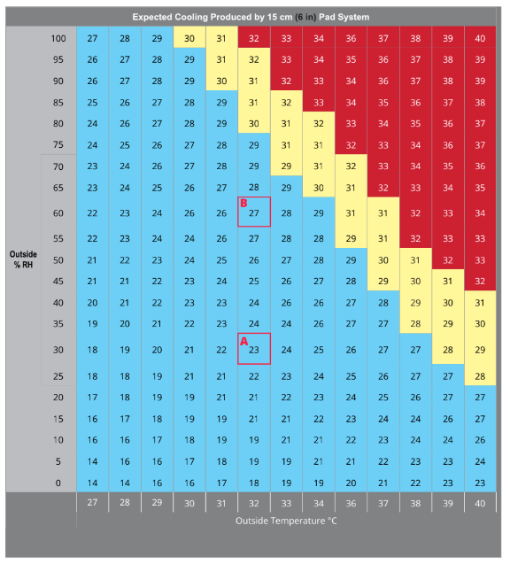
The table is an example of an evaporative cool pad with an efficiency rating at 75 % and it’s potential cooling capacity over a range of outside temperatures and relative humidity levels. In the table (below), colored cells indicate cooling potential as follows:
Blue - acceptable cooling
Yellow - marginal cooling
Red - insufficient cooling
For every 1 °C of cooling produced by the evaporative cooling system, the % RH of the air will increase approximately 4.5 % (1 °F = 2.5 % RH increase).
Two Examples – external ambient temperature 32 °C and external relative humidity at 30 and 60 %.
A.
32 °C and 30 % RH:
Potential reduction in house temperature is 9.4 °C
Added humidity: 4.5 % × 9.4 °C = 42 %
New combined inside humidity: 30% (outside) + 42 % = 72 %
B.
32 °C and 60% RH:
Potential reduction in house temperature is 4.7 °C
Added humidity: 4.5 % × 4.7°C = 21 %
New combined inside humidity: 60 % (outside) + 21 % = 81 %
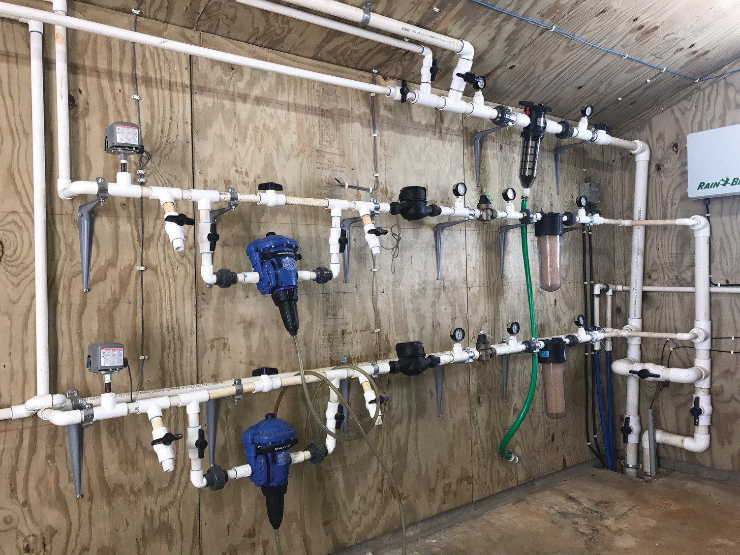
Water Meters
Monitoring water consumption with water meters is an excellent means of gauging feed consumption, as the two are highly correlated. Do not use oversized meters that require significant flow rates to register consumption, which is especially relevant during the 1st few weeks. Water meters should be sized the same as the incoming water supply line to ensure adequate flow rate.
Water consumption should be evaluated at the same time each day to determine general performance trends and bird well-being. Water consumption per bird should be recorded every 24 hours. Any substantial change in water usage should be investigated as this may indicate a water leak, health challenge or feed issue. A drop in water consumption is often the first indicator of a flock problem.
Note: Install a water meter bypass, used during flushing – water used during regular flushing procedures should not be included in the daily water intake reading.
Water Storage Tanks
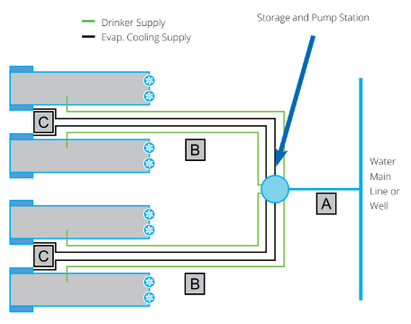
Adequate water storage should be provided on the farm in the event that the main system fails. A farm supply of water equal to the maximum 48 hour demand is ideal. The storage capacity is based on the volume of water for the number of birds required for the evaporative cooling system. When designing or upgrading a farm, understanding water supply and layout is critical.
Separate water supplies for the birds and cooling systems should be installed in each house. Take into account the peak drinking demand requirements and evaporative cooling system demand. Storage tanks should be housed in a separate insulated building, or alternatively shaded and insulated. If the source of water is a well or holding tank, the supply pump capacity should match the birds’ maximum water consumption and also the maximum needs of the fogging and/or evaporative cooling systems.
The diagram below is an example of the water supply layout for a 4 house farm
Pump pressure at source: 3.5 to 4 bar (50 to 60 psi)
A = 75 mm (3 in) pipe diameter and 300 l/min
B = 50 mm (2 in) pipe diameter and 150 l/min
C = 40 mm (1.5 in) pipe diameter and 75 l/min
Control room: 2.8 bar (40 psi) - minimum
Drinkers: 2 bar (30 psi)

Evaporative cooling pad water requirements will depend on outside temperature and relative humidity. The table (below) is an example of how evaporative pad water requirements increase with a drop in relative humidity at 35 °C (95 °F).

The following table is an example of the maximum cooling pad water requirement of a modern tunnel ventilated house operating at an airspeed of 3 m/s (600 fpm).

Light Trap Function and Installation
Designing a ventilation system for a dark out tunnel ventilated rearing house can be challenging. There are many different models and designs of light traps available, each with different light restriction capacities. The air flow restriction does not necessarily correspond with the light reduction factor. Some very high light reducing traps have very low air flow restrictions. The required house air velocity and the fan capacity will dictate the area of light trap needed.
Light traps or light filters can be compared in terms of two criteria:
- Resistance to air flow: Resistance to air flow is presented in graphical format with static pressure (pascal or inches water) plotted against light trap face velocity in m/s or fpm. When comparing light traps at a given face velocity, a lower static pressure will indicate a lower air flow resistance.
- Resistance to light transmission: Test facilities will place high wattage lamps outside the light traps to simulate direct sunlight. Light intensity is measured at the outside and inside surfaces of the light traps. The light reduction factor is calculated by dividing the outside light intensity by the inside light intensity.
When comparing different light traps/filters, the higher the light reduction factor, the greater the resistance to light transmission. The light trap should have a light reduction factor of at least 2,000,000 to one. Ideally it should be in excess of 10,000,000 to one. An excellent reference can be found at http://bess.illinois.edu/pdf/Lightraps.pdf
Some general light trap installation and management tips:
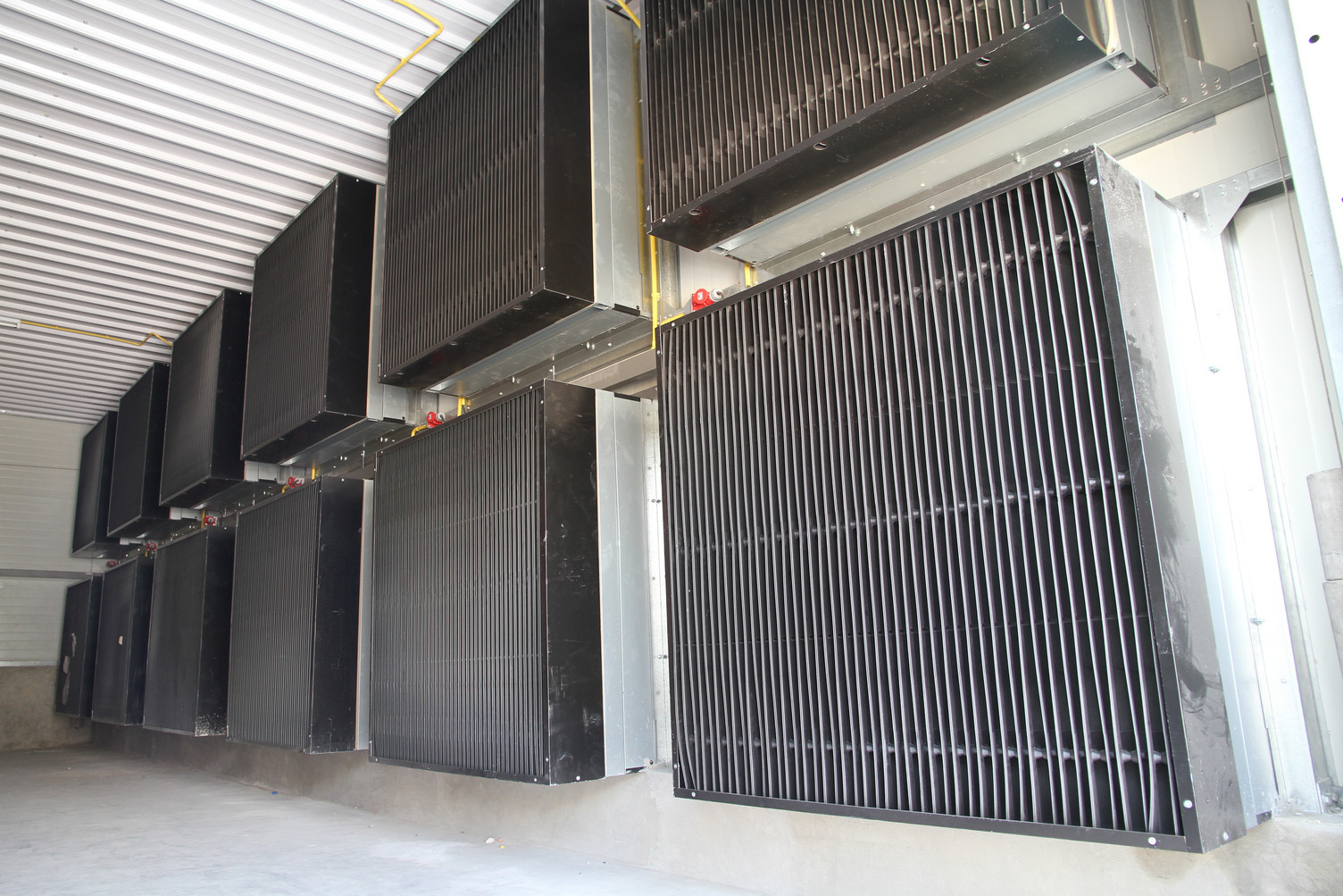
- Light traps are usually available in cellular or blade type (photo right blade type).
- When installing light traps, it is very important to know the pressure drop across the light trap, to ensure the correct fan capacity is installed to meet the air velocity requirements of the flock.
- The light trap supplier will supply the expected pressure drops (in wc or Pa) over a range of face velocities (fpm or m/s).
- The airspeed through the light trap (face velocity) will always depend on the area of the light trap installed.
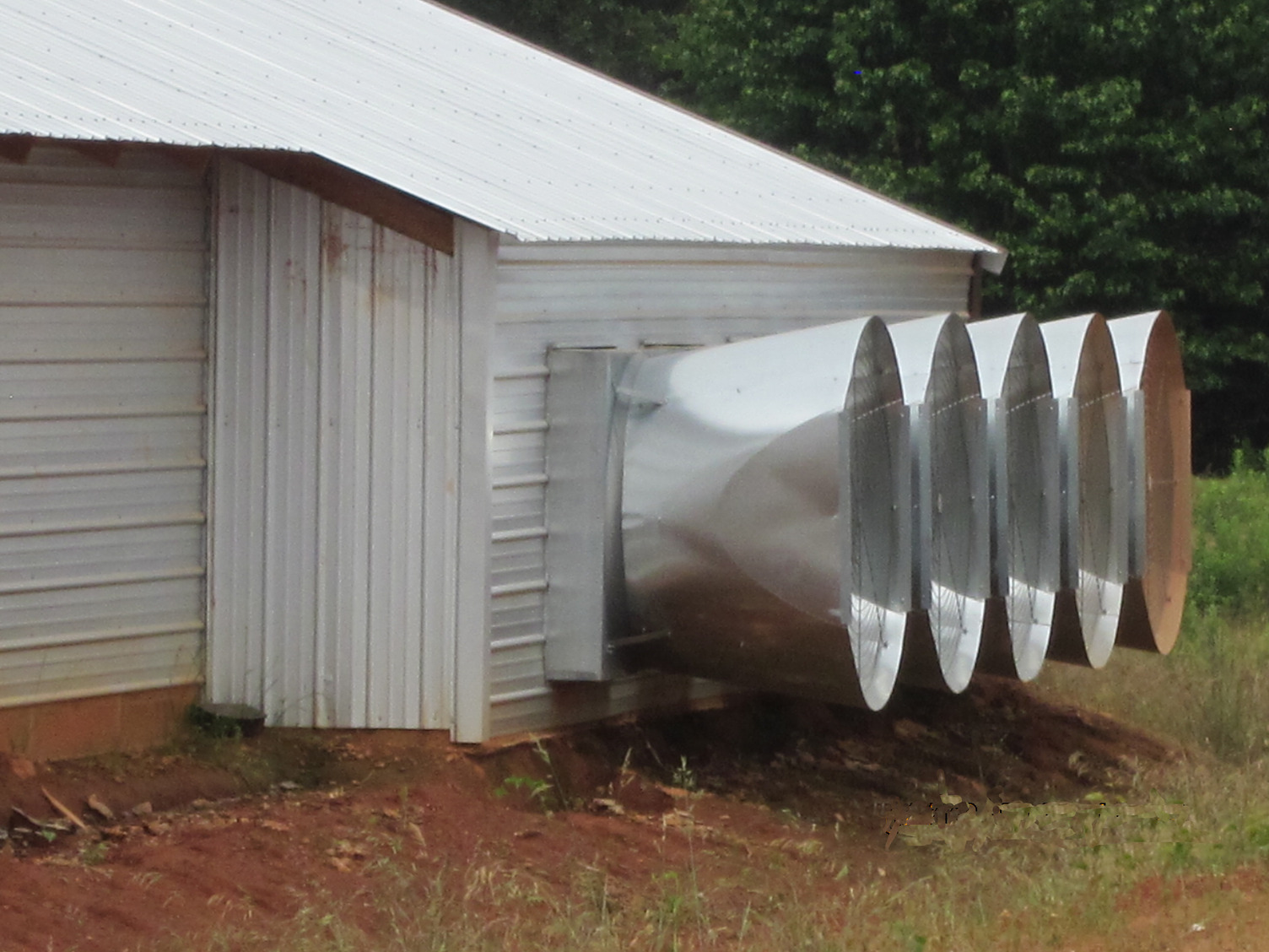
- Light traps placed directly over fans will cause a significant drop in fan performance, thus they are not the best option in a high-speed tunnel houses (image below).
- In a cross ventilated pullet house, a 150 cm × 150 cm or 2.25 m2 (60 in x 60 in or 25 ft2) light trap can be placed directly over a standard 120 cm fan (48 in).
- When installing both tunnel inlet light traps and evaporative pads in a pullet rearing house, the tunnel inlet light traps can have a lower light reduction factor and lower air flow resistance than those installed at the tunnel fan end, due to the light reduction factor offered by the evaporative pads and a darkened dog house (painted black or the use of shade cloth).
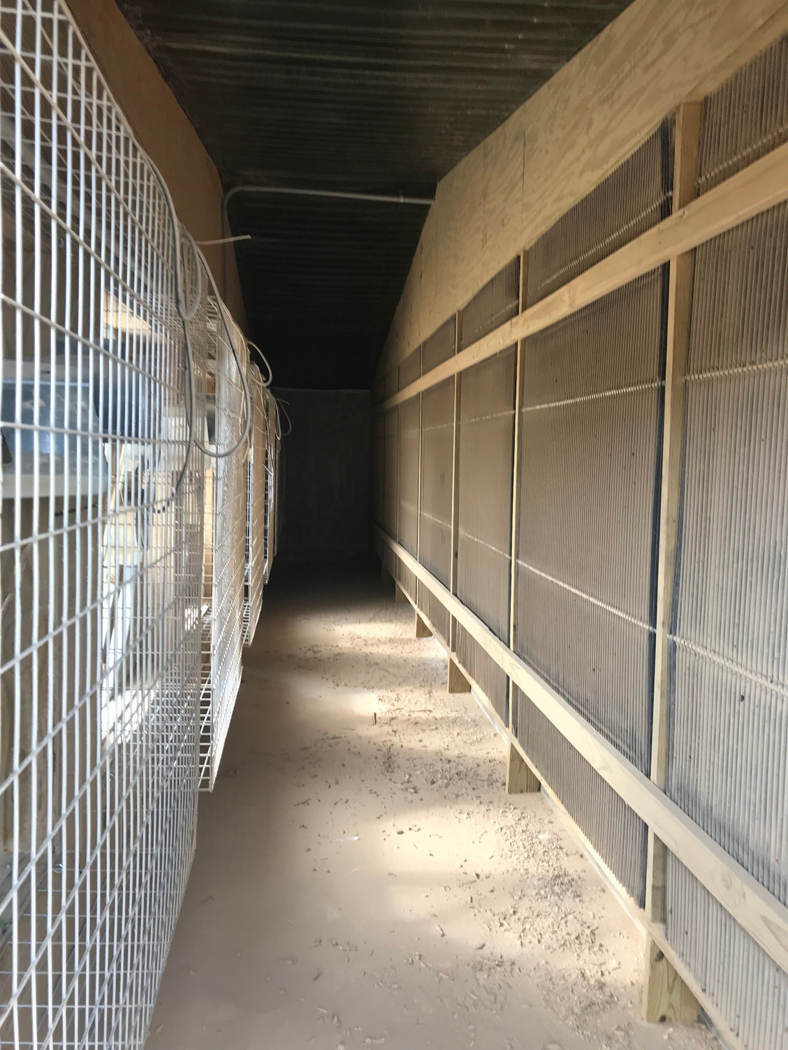
- An efficient installation option for the tunnel fan light traps, is to construct a false wall that incorporates the light traps, placed 1.5 m (5 ft) from the tunnel fan end (image right). This allows air to pass through all light traps reducing the pressure drop when the house is not in full tunnel mode.
- An alternative is to install the tunnel fans on the sides of the house, each with a plenum type room (doghouse) for the installation of the light trap false walls (image below). This is by far the most efficient, since fan and light trap area requirements in high speed rearing houses usually require more light trap area than can fit into the house cross section.
