

Cobb Breeder Management Guide: Minimum ventilation and perimeter inlet management
Learn more about negative pressure and perimeter inlets for ventilationPart of Series:
< Previous Article in Series Next Article in Series >
Editor's note: This article is an excerpt from the Cobb Breeder Management Guide and additional articles will follow. The Guide was designed to highlight critical factors that are most likely to influence flock performance. The management recommendations discussed were developed specifically for Cobb products. The recommendations are intended as a reference and supplement to your own flock management skills so that you can apply your knowledge and judgement to obtain consistently good results with the Cobb family of products. To read or download the complete Guide or to view Cobb's other management guides, click here.
The minimum ventilation system must have sufficient capacity to operate for the full life of the flock. The following is an example calculation of the number of fans required. The minimum ventilation calculations are only guidelines. Daily adjustments should be made based on air quality and humidity. The range and capacity of fans to be used for cycle ventilation will increase over time until all installed minimum ventilation fans are used.
Calculations for the minimum number of fans required for ventilation in a typical tunnel house
Sample fans
- Fans capacities used in the examples are rated at 25 pa (0.1 in wc)
- Exhaust or side wall fans: 900 mm (36 in), working capacity of 340 m3/min (12,000 cfm).
- Air exchange range: 0.3 to 0.60 m3/min per m2 of floor area (1 to 2 cfm per ft2 of floor area).
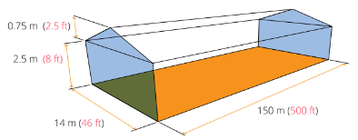
Sample house dimensions
House dimensions: 150 m long, 14 m wide and 2.88 m average height
House dimensions: 500 ft long, 46 ft wide and 9.25 ft average height
Average height = 2.5 m + (0.5 x 0.75 m) = 2.88 m
Average height = 8 ft + (0.5 x 2.5 ft) = 9.25 ft
House floor area: 150 m × 15 m = 2,100 m2
House floor area: 500 ft × 46 ft = 23,000 ft2
(House floor area X Air exchange rate) ÷ Working capacity = Number of fans required
Number of fans required for air exchange range of 0.3 to 0.6 m3/min per m2
2,100 m2 × 0.3 to 0.6 m3/min per m2 of floor area = 630 to 1260 m3/min
630 to 1260 ÷ 340 m3/min = 1.85 to 3.70 or 2 to 4 fans
Number of fans required for air exchange range: 1 to 2 cfm/ft2
23,000 ft2 × 1 to 2 cfm per ft2 of floor area = 23,000 cfm to 46,000 cfm
23,000 cfm to 46,000 cfm ÷ 12,000 cfm = 1.91 to 3.83 or 2 to 4 fans
Negative Pressure - Key Requirement for Minimum Ventilation
The most efficient way to accomplish air distribution for minimum ventilation is by using a negative pressure ventilation system. The pressure drop across the inlets and amount the inlet is opened should be adjusted to ensure that the incoming air jet attaches to the ceiling and reaches the peak of the house where the heat has accumulated.
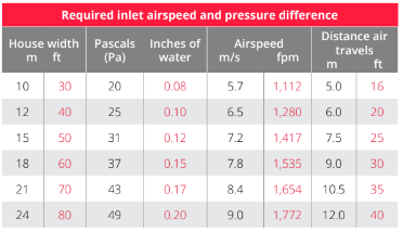
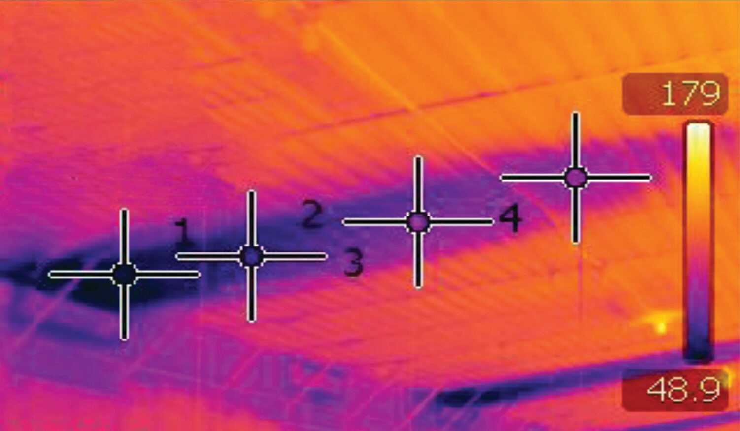
The table (below) can be used as a reference guide to determine the required inlet pressure drop. The pressure drop selected will depend on the house width, how far the incoming air jet must travel once it enters the house, and the outside temperature. When outside temperatures are below 5 °C (40 °F) the inlet pressure drop and opening size will need to be increased. The ability of the incoming air jet to attach to the ceiling depends on the temperature differentials between outside and inside the house. Always use a smoke test to ensure that the incoming air reaches the center of the house. Smoke tests should only be done when the outside temperatures are significantly colder than inside, and when there is no wind.
In houses with obstructions such as purloins or electrical conduit which can interrupt the incoming air jet, smooth solid ramps of about 3 m (9 ft 10 in) need to be installed in front of the perimeter inlets.
Note: In houses with side wall (perimeter) inlets that are positioned lower on the wall, the pressures and inlet openings need to be increased accordingly to ensure the incoming air jet reaches into the center of the house. This is especially important with low outside temperatures.
Perimeter Inlet Management and Installation
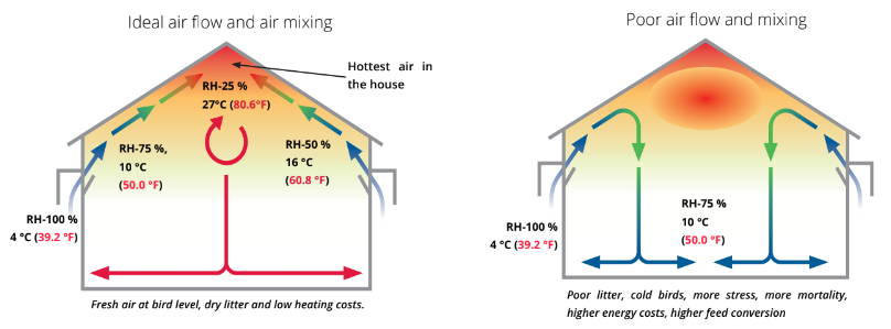
Perimeter inlets are arguably the most important part of the house ventilation system. Positioning and design of the inlets will significantly impact the direction of the incoming cold air. During cool seasons, fresh air (cooler and heavier) that enters the house mixes with warm, dry air before reaching the level of the birds. While mixing, the temperature of the incoming air increases and humidity decreases. The perimeter inlets are one tool that can initially manage the incoming air. With these, the airflow can be directed in a way that allows the air to gain heat and decrease humidity as it flows into the center of the house. For every 11 °C or 20 °F increase in temperature the relative humidity will be halved.
The most common consequence of poorly managed inlets is the humidification and compaction of the litter, primarily along the side walls. A well-designed inlet should close and seal completely when the fans are off. When open, the air should only enter over the top of the inlet and not from the sides or the base of the inlet. Inlets that leak air through the sides and base will direct cold air to the floor, resulting in chilled birds and condensation.
Inlet openings should be pressure controlled to maintain a constant airflow at different fan capacities. When cables are being used to operate the inlets, special attention needs to be given to the nylon cords which are closing the inlets. Cables can stretch and are prone to cause uneven openings. Inlets that do not close completely will cause heat and energy losses, especially under windy conditions. An 8 mm steel rod is the preferred material to be used when installing the inlets.
The inlets used for minimum ventilation need to open enough to achieve the required static pressure and air jet. Depending on the inlet design, a minimum opening of 2.5 cm to 5 cm (1 to 2 in) is required to ensure cold incoming air jets attach to the ceiling and detach near the center. Always smoke test the house in cold weather or attach a series of ribbon tapes to the ceiling from in front of the inlet to the center of the house. Place these ribbons at an inlet close to the control room for easy observation.
Simple Negative Pressure Test
To effectively generate a negative pressure system in a controlled environment rearing or production house, the house needs to be as airtight as possible. Typically, leaks are located along the roof ridge, close to the fans, around doors and along stem walls. In curtain sided rearing and production houses, the curtains are usually the largest source of leaks.
Test the effectiveness of how well the house is sealed by closing all the inlets, then measure the pressure drop across any inlet or door. Turn on the equivalent of 0.30 m3/min (18 m3/hr per m2 of floor area) or (1 cfm per ft2 of floor area) of fan capacity per the floor area. A pressure in excess of 37.5 Pa (0.15 in wc) should be recorded across the opening. Pressure < 25 Pa (0.10 in wc), indicates the house is poorly sealed.


