

Cobb Breeder Management Guide: Transition and tunnel ventilation
Learn more about fan capacity and inlets for full transitionPart of Series:
< Previous Article in Series Next Article in Series >
Editor's note: This article is an excerpt from the Cobb Breeder Management Guide and additional articles will follow. The Guide was designed to highlight critical factors that are most likely to influence flock performance. The management recommendations discussed were developed specifically for Cobb products. The recommendations are intended as a reference and supplement to your own flock management skills so that you can apply your knowledge and judgement to obtain consistently good results with the Cobb family of products. To read or download the complete Guide or to view Cobb's other management guides, click here.
Transition Ventilation
Transition ventilation begins to operate when the house thermostat overrides the cycle timer to allow continuous running of the cycle fans and the staging of the remaining transition fans to control temperature. Transition ventilation is the temperature control stage between the minimum ventilation stage and tunnel ventilation. The key function of transition ventilation is to increase house air exchange and manage temperature without creating high airspeeds or velocity at bird level. The maximum airspeeds, generated in full transition mode, can range from 25 to 50 % of full tunnel ventilation capacity in modern tunnel ventilated houses. It is a vital stage of ventilation in tunnel ventilated houses to ensure bird comfort and early feed intake, especially in rearing. Flock uniformity always starts in the 1st week and is driven by early feed intake and temperature management.
Fan capacity requirement for full transition
In typical pullet and production tunnel houses, the transitional ventilation system typically uses 30 to 50 % of the total tunnel ventilation capacity. In colder climates, having more transition capacity is beneficial. The capacity can also be expressed in terms of floor area: 1.2 to 1.8 m3 /min per m2 of floor area (4 to 5 cfm per ft2 of floor area) or air exchange rates of 2 to 3-minutes when in full transition.
- These fans use perimeter wall inlets that are evenly distributed lengthwise down the house. The inlets are most efficient when controlled by negative pressure. This system gives excellent temperature control, reduces the risk of chilling the birds, and is a valuable part of any ventilation system.
- During the final stage of transition ventilation (full transition), the inlets are in their fully opened position and the tunnel inlet will open to provide additional incoming air to match the fan requirement and balance the static pressure.
How many inlets for full transition?
- Depends on - capacity of a single inlet at a specific static pressure.
- Depends on - the air exchange requirement in full transition mode.
- In cold climates, pullet and breeder production houses that do not have a tunnel ventilation system will use perimeter wall inlets for all levels of ventilation. These houses should have a maximum air exchange capacity of less than 1 minute to cope with hot conditions.
- During the final stage of transition the tunnel inlet opens to balance static pressure.
- Tunnel ventilation can be delayed by operating more fans through both the perimeter wall and tunnel inlets. These further stages, sometimes referred to as tunnel assist mode, allow significant increases in air exchange without dramatic increases in airspeeds at floor level.
- For the house to transition to tunnel ventilation, the outside temperature needs to be warm – above 25 °C (77 °F).
Calculating transition ventilation inlet capacity
Sample fans
Fans capacities used in the examples are rated at 25 pa (0.1in wc)
900 mm (36 in), working capacity of 340 m3/min (12,000 cfm)
1,270 mm (50 in), working capacity of 680 m3/min (24,000 cfm)
Fan requirement based on house floor area: 1.2 to 1.8 m3/min/m2 (4 to 5 cfm/ft2)
Sample house dimensions
House dimensions: 150 m long, 14 m wide and 2.88 m average height
House dimensions: 500 ft long, 46 ft wide and 9.25 ft average height
Average height = 2.5 m + (0.5 x 0.75 m) = 2.88 m
Average height = 8 ft + (0.5 x 2.5 ft) = 9.25 ft
House floor area: 150 m × 15 m = 2,100 m2
House floor area: 500 ft × 46 ft = 23,000 ft2
Example calculation of how many fans are needed using fan capacity of 680m3/min (24,000 cfm)
Floor area × 1.2 to 1.8 m3/min per m2 (4 to 5 cfm per ft2) = number of fans needed
2,100 m2 × 1.2 to 1.8 m3/min = 2,520 to 3,780 m3/min = 4 to 5 fans needed
23,000 ft2 × 4 to 5 cfm/ft2 = 92,000 to 115,000 cfm = 4 to 5 fans needed
How many inlets needed for transition ventilation?
Example calculations of how many inlets are needed using an inlet capacity of 34.5 m3/min (1,218 cfm) at 25 Pa
Note: If inlet capacity is unknown use the following assumptions: Standard inlet capacity = 7229 m3/min per m2 (750 cfm per ft2) of inlet opening at 25 Pa (0.10 in wc).
Step 1: Total Transition Fan Capacity = Number of fans needed X Fan capacity
5 × 680 m3/min (24,000 cfm) =
3,400 m3/min or 120,000 cfm
Step 2: Number of inlets = Total Transition Fan Capacity ÷ Inlet Capacity
3,400 m3/min (120,000 cfm) ÷ 34.5 m3/min (1,218 cfm) =
108 inlets or 54 inlets per side (common practice to add extra 10 % inlet capacity)
Tunnel Ventilation
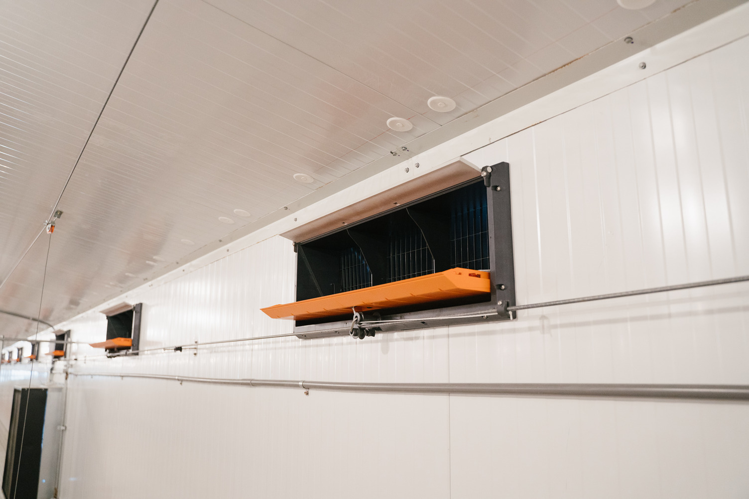
Tunnel ventilation is used in hot weather for cooling - the process of removing metabolic heat from the pullets and breeders. The tunnel ventilation fans are placed at one end of the house with the air intake at the opposite end. The air flow creates a wind-chill effect, which produces the effective temperature experienced by the bird. The effective temperature experienced will depend on airspeed, bird age, relative humidity and numerous other factors and can range from 1 to 8 °C below ambient temperatures. Bird effective temperatures should be maintained below 30°C (86°F).
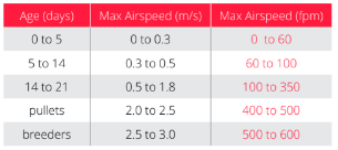
To ensure maximum bird activity and feed intake, during brooding and the first few weeks of the rearing phases, keep airspeeds within the limits given in the table below, unless air temperatures are well in excess of target temperatures for the specific ages. Tunnel fan capacity or air exchange rate should be sufficient to ensure an absolute maximum temperature pickup or differential (ΔT) of 2.8°C (5 °F) from the front to the end of the house on the hottest day.
Understanding negative pressure measurements in full tunnel mode
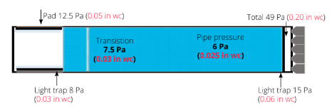
The pressure readings will increase from the front to the extraction end of the house. The pressure reading at the extraction end is an indication of the amount of work the fans must do to move the air down the length of the house. It is a sum of the following pressure drops:
- Pad pressure
- Inlet light trap
- Tunnel inlet curtain or door pressure drop
- Transition or “squeeze” pressure
- Pipe pressure, which includes resistance created by objects such as nest boxes and feed hoppers
- Tunnel fan light trap
Estimated fan operating pressure in dark out pullet house with evaporative cooling
Pad pressure + inlet light trap + transition + pipe + fan light trap
= 12.5 Pa + 8 Pa + 7.5 Pa + 6 Pa + 15 Pa = 49 Pa
= 0.05 in wc + 0.03 in wc + 0.03 in wc + 0.025 in wc + 0.06 in wc = 0.20 in wc
Key points when choosing or comparing tunnel fans
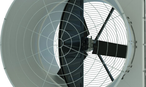
- The fans most suitable for a tunnel ventilation system are high capacity cone fans with minimum diameters ranging from 1.27 m (50 in) to 1.42 m (6 in) or more
- All ratings must be at a minimum pressure of 25 Pa (0.10 in wc)
- Energy efficiency should be 0.0109 m3/s (23 cfm) per Watt
- Air flow ratio: > 0.75 indicator of how well the fan holds up under high static pressures 12.5 to 50 Pa (0.05 to 0.2 in wc)
- Fans should be sealed to prevent air leaks when not operational
- Fans should be purchased on efficiency and build quality – not price
Adjusting tunnel inlet for correct air distribution
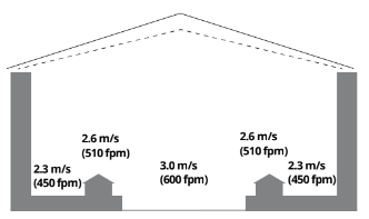
The diagrams (below) illustrate the importance of maintaining the correct airspeed and negative pressure drop at the tunnel inlet curtain or door. Very low inlet airspeeds and pressure drops will result in increased “dead spots” (this refers to areas in the house near the walls that have minimal airspeed or in US style production houses on the slats between the nest box and the side wall curtain). The tunnel inlet door or curtain pressure drop must be adjusted to help reduce this phenomenon. If air speeds are not improved temperatures will be higher in these areas and the flock could be subject to heat stress.

Calculations for tunnel ventilation rates

Sample house dimensions
House dimensions: 150 m long, 14 m wide and 2.88 m average height
House dimensions: 500 ft long, 46 ft wide and 9.25 ft average height
Cross section: 14 m wide x 2.88 m average height = 40.32 m2
Cross section: 46 ft wide × 9.25 ft average height = 425.5 ft2
House volume: 150 m long x 14 m wide x 2.88 m average height = 6048 m3
House volume: 500 ft long x 46 ft wide x 9.25 ft average height = 212,750 ft2
Sample fans
Example for production house: 3 m/s (600 fpm)
Fans capacities used in the examples are rated at 25 Pa (0.1in wc).
1,270 mm (50 in, working capacity of 680 m3/min (24,000 cfm).
Step 1: Fan capacity required to achieve an airspeed of 3.0 m/s (600 fpm) at 25 Pa (0.10 in wc)
Required fan capacity = Cross section × Airspeed
40.32 m2 x 3.0 m/s = 120.96 m3/s or 7,257 m3/min
425.5 ft2 × 600 fpm = 255,300 cfm
Number of 1.27 m (50 in) fans required:
7,257 m3/min ÷ 680 m3/min = 10.67 or 11 fans
255,300 cfm ÷ 24,000 cfm = 10.63 or 11 fans
Step 2: House air exchange should be between 40 and 50 seconds
Air Exchange = House Volume ÷ Total Fan Capacity
6,048 m3 ÷ (11 x 680 m3/min) = 6,048 m3 ÷ 7,480 m3/min = 0.80 min or 49 seconds
212,750 ft3 ÷ (11 × 24,000 cfm) = 212,750 cfm ÷ 264,000 cfm = 0.80 min or 49 seconds
Step 3: Is the airspeed adequate?
Airspeed = Total Fan Capacity (m3/min) ÷ Cross Section Area (m2)
(11 x 680 m3/min) ÷ 40.32 m2 = 186.0 m/min or 3.00 m/s
(11 x 24,000 ft3/min) ÷ 425 ft2 = 620 fpm
Improving airspeed distribution in breeder houses
Airspeed Distribution - Mechanical Nest Boxes
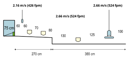
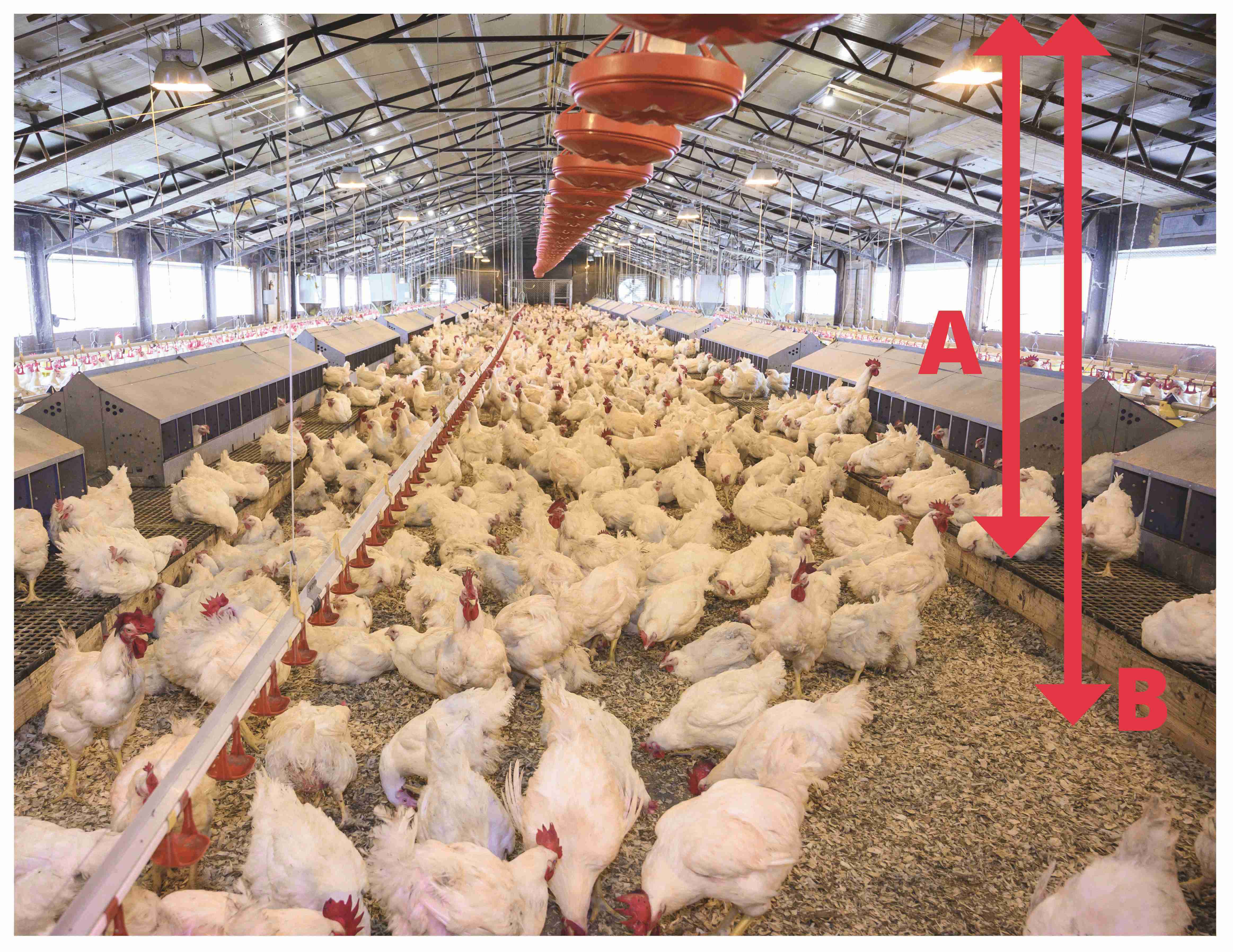
In full tunnel ventilation mode, the air moving down the production house will always find the path of least resistance. Airspeed distribution can be challenging in breeder production houses due to the presence of equipment. The placement of feed distribution hoppers and the orientation of nest boxes plays a major role in airspeed uniformity across the house cross section.
- In USA type breeder houses, with a central scratch area, the air velocities on the slats are typically 15 to 25 % lower than the center air velocity in the scratch area.
- Low slat air velocities result in significantly less bird-heat removal. Scratch areas can be significantly cooler. Further, increasing tunnel fan capacity or velocity will increase this differential, with the greatest improvements always seen in the scratch area.
- Airspeeds are always the lowest against the side walls.
- Prevent using exposed structural posts on the side walls. Smooth, solid side walls instead of curtains will improve slat airspeeds.
Community Nest Setup Airspeed Distribution
